
No Products in the Cart

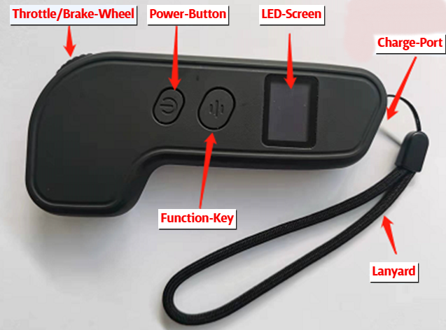


Wireless Thumb Throttle Smart Remote
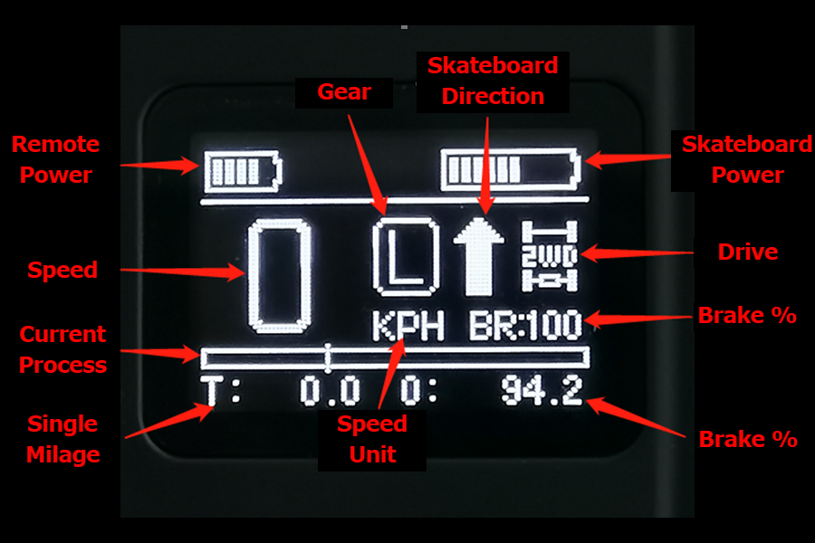
Remote LED Screen
2.1 Riding Modes: Street, All-Terrain, and Road Racing
Read this section to the end before riding the SE1.
Your SE1 offers four riding modes via the thumb throttle remote: Low (L), Eco (E), Sport (S), and Sport+ (S+). Each mode adjusts motor output, acceleration response, brake power, and top speed. The corresponding environment and terrain type require the rider to select a speed mode on the remote that matches their ESK8 riding ability and experience to the SE1 or SE1 Dragon e-board's performance.
Low and Eco Mode (Beginner, up to 15 mph): This mode is ideal for casual street riding on smooth pavement. It can also be for relaxed, low-stress riding in urban areas or parks.
Sport Mode (Intermediate, up to 30 mph): Suited for all-terrain riding, including grassy fields or dirt paths. Balances power and responsiveness for varied surfaces.
SuperSport + Mode (Advanced, 30+ mph): Designed for experienced riders on smooth surfaces and road racing. Unleashes complete motor potential.
How to Switch Modes: Press the function button once on the remote to select a different mode.
For more information about the remote settings and adjustments, see section 7.6
2.2 Proper Stance and Balance
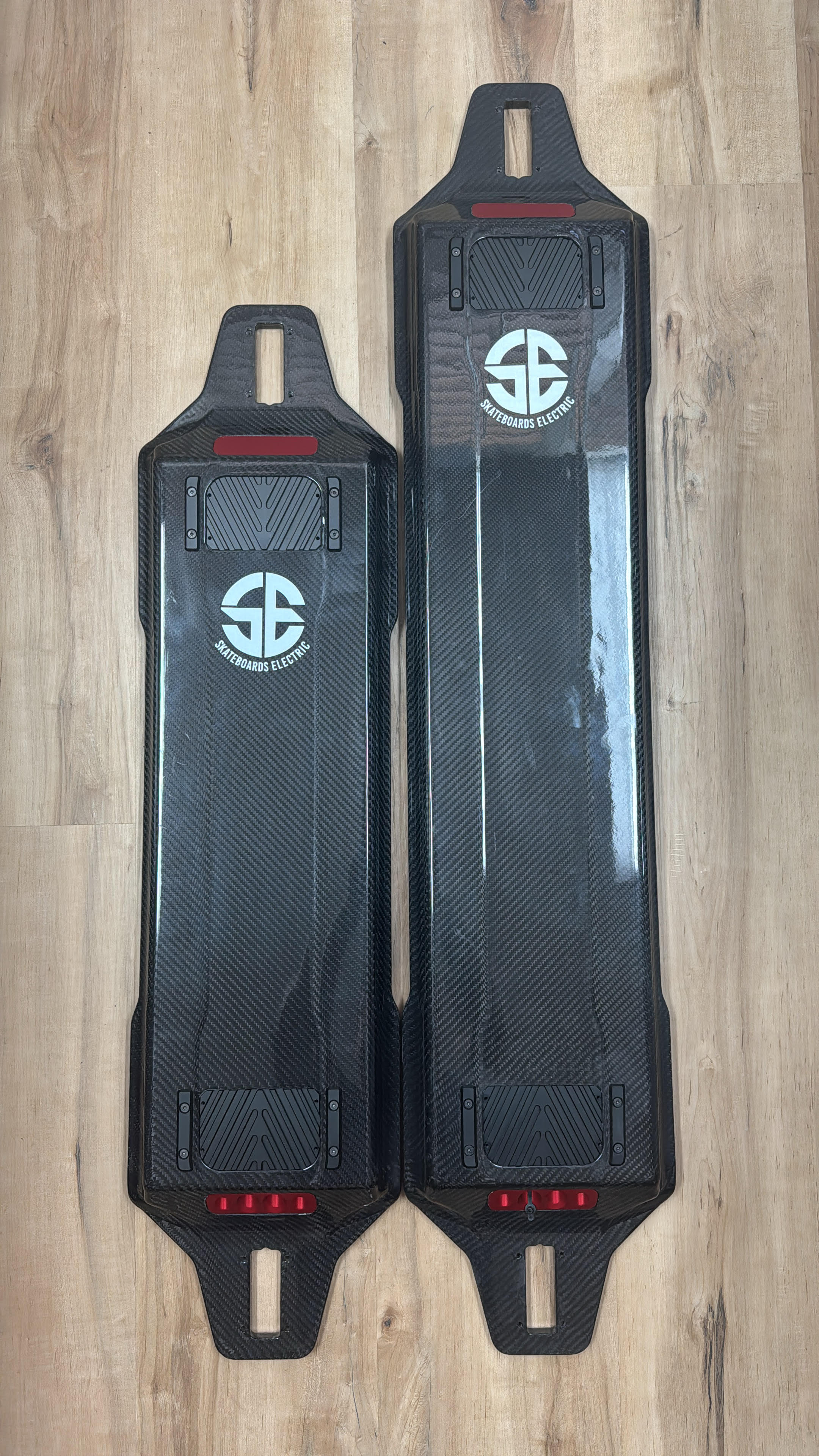
A solid stance with feet as far forward and as far back as comfortably possible maximizes control and comfort on the SE1’s standard- and XL9-length carbon fiber deck.
Body Position: Keep knees slightly bent and some extra weight on your front leg. Lean slightly forward when accelerating and lean back when braking.
Tip: Steer the deck primarily with your front foot and fine-tune the ride for precise balance with your rear foot.
2.3 Cornering and Turning Techniques
Basic Turning: Lean on your toes or heels gently in the direction you want to go. The trucks’ pivot shafts, bearings, solid axle, and spring-loaded tie rods respond when weight shifts left or right.
Hairpin or Wide High-Speed Turns: Increase the tie rod angles for extra-tight lower-speed corners and a smaller turning radius. (Section 4.2) Decrease the tie rod angles for improved stability at higher speeds during turns. The default settings for the front and rear trucks are set to the lowest tie rod angle option for maximum high-speed stability.
Bushing Adjustments: If the deck feels twitchy when turning or decelerating, tighten the bushings (Section 5.3) for a stiffer, more supportive response. If the bushings are already tight, loosen them to find the perfect bushing pre-load tension for your weight. (Section 4.3)
2.4 Accelerating and Braking Safely
Acceleration: Gradually push the thumb throttle forward. In Eco mode, expect smooth starts. Sport mode offers a quicker response, while S+ mode delivers smooth, aggressive power.
Braking: Slowly pull the throttle back to engage regenerative braking. Start with light pulls to slow down, then increase the pressure to achieve a complete stop.
2.5 Navigating Uneven Terrain and Low-Traction Surfaces
Low-Traction Surfaces (e.g., wet pavement, loose dirt): decrease speed mode and reduce speed. Avoid sharp turns or sudden acceleration.
Warning: Avoid deep puddles or heavy rain, even with IPX-6 resistance. Water ingress can damage the battery or ESC. Never ride over obstacles and speed bumps taller than 2.5 inches to prevent deck damage.
-
Check tire pressure and add air to the four tires before every ride. 30-35 psi is best.
-
Before pressing the power button on the e-board, turn your remote on with the power button.
-
Press the power button on the underside of the e-board deck near the rear trucks. The remote will show the whole dashboard. Confirm that the wheel direction and speed mode are correct, and you're ready to go. To switch the motor wheel's direction of travel, press the function button twice.
Warning: Always turn the power to the remote off when not riding the e-board to prevent accidental throttle engagement and a runaway e-board.
3.1 Battery Maintenance and Safety
Follow these best practices to maximize safety and lifespan.
3.1.1 Charging Guidelines
Charge Correctly: Plug into a 110-240V outlet, connect to the board’s charging port, and charge in a cool (50-77°F / 10-25°C), dry place. LED turns green when fully charged (2-4 hours).
Avoid Overcharging: Unplug the charger to prevent cell stress when not in use.
Pre-Ride Charge: Charge to 100% before rides for maximum range. Partial charges (75-80%) are sufficient for daily use to extend the lifespan, but are not critical due to the durable nature of lithium-ion batteries.
Tip: When starting a ride with a fully charged battery, avoid riding down steep hills with heavy regenerative braking. Overcurrent from regenerative braking can cause brake failure and damage the BMS (Battery Management System).
3.1.2 Battery Storage and Long-Term Care
Short-Term Storage: Store at 50-68°F (10-20°C) with 60% charge. Avoid extreme heat or freezing temperatures.
Long-Term Storage: Charge to 60% every 3 months to prevent deep discharge. Store in a dry, non-flammable environment.
Avoid Damage: Do not drop, puncture, or expose the battery to water beyond IPX-6 limits.
Tip: Never allow a dead battery to sit fully discharged. Charge it as soon as possible to maintain a charge at all times.
3.1.3 Battery Specifications
14S4P Samsung 25S: 12-mile range, 2-hour charge, 50.4V, 10Ah. 2500mAh
14S4P Samsung 50S: 20-mile range, 3-hour charge, 50.4V, 20Ah. 5000mAh
14S6P Samsung 50S: 30-mile range (XL9 deck), ~4-hour charge, 50.4V, 30Ah, 5000mAh
16S3P Molicel P45B: 20-mile range, 2-hour charge, 45A high rate discharge. 4500mAh (not compatible with 6350 2000W motors)
16S5P Molicel P45B: 30-mile range, 3-hour charge, 45A high discharge.4500mAh (not compatible with 6350 2000W motors)
Warning: Never attempt to open or modify the battery, and do not use it if the cells have noticeable dents or punctures. Contact support if an issue arises. Mishandling can cause fire or injury.
3.2 Cleaning and Water Resistance (IPX-6)
The SE1’s IPX-6 rating protects against light rain and splashes but not submersion.
Cleaning: Wipe the deck with a damp cloth and mild soap. Use a soft brush for tire treads. Dry thoroughly with a microfiber cloth.
Charging Port: Ensure the port cover is sealed before and after cleaning, especially when riding in wet conditions.
Avoid: High-pressure water, submersion, or harsh chemicals that can degrade seals or coatings.
Tip: To maintain maximum water resistance, apply a silicone sealant under the battery box lid where it sits on the deck.
Warning: Water damage from submersion voids the warranty. Stop riding if the deck is submerged or if critical components get swamped.
3.3 Tire Maintenance and Replacement
The 160mm x 72mm tires (street tread or bald racing) require regular checks to maintain grip and safety.
Pressure Check: A gauge ensures 30-35 psi before each ride. Bald racing tires at 30 psi for max-grip corner speed traction.
Inspect: Look for cuts, punctures, or uneven wear. Replace if the tread depth is low or the tires are bald and down to the cords.
Replacement: Remove the wheel using the provided wrench, deflate all the air from the tire, press and turn the outer ring bead lock until it slides off the wheel hub, swap the tire and/or tube, and reinstall the wheel with proper alignment.
Tip: Carry a portable tire inflator for pre-ride inflation and on-the-go adjustments.
Warning: Under- or over-inflated tires reduce traction and durability.
3.4 Hardware Inspection
Pivot shaft trucks are durable, but they require pre-ride checks to prevent potential issues.
Trucks and Axles: Check for loose nuts, bolts, bearings, and belts for misalignment. Use the squaring string (Section 5.4) after bumpy long rides and truck disassembly to verify axles are square and aligned with the deck.
Tie Rods: Ensure the steering tie rod jam nuts are tight. The springs require adequate pre-load without allowing loose or sloppy play. Adjust if loose or out of alignment (Section 5.2).
Pre-Ride Checklist:
-
Tug on trucks and wheels to confirm tightness.
-
Spin wheels to detect wobble or grinding.
-
Adjust tire pressures.
-
Test remote response and ESC function.
Tip: Keep a small tool kit for on-the-go bolt tightening.
3.5 Lubricating Bearings and Bushings
Regular bearing and bushing lubrication prevents wear.
Frequency: Lubricate every 50 miles or monthly, more often in dusty or wet conditions.
Process:
-
Remove the wheels with the provided wrench.
-
Clean bearings with a cloth to remove dirt.
-
Apply 2-3 drops of WD-40 (or similar oil-based lubricant) to each bearing.
-
Spin bearings by hand to distribute lubricant.
-
Reinstall wheels and tighten.
Check: Spin wheels to ensure they rotate freely without grinding or loose play.
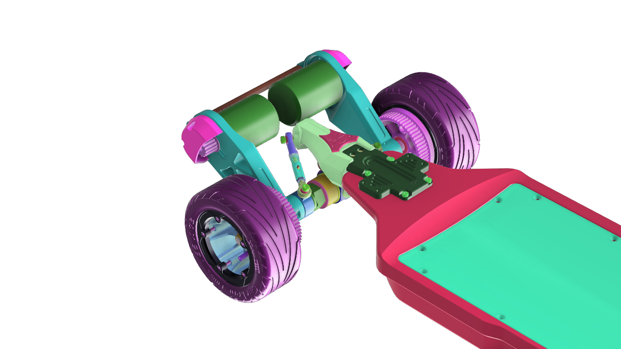
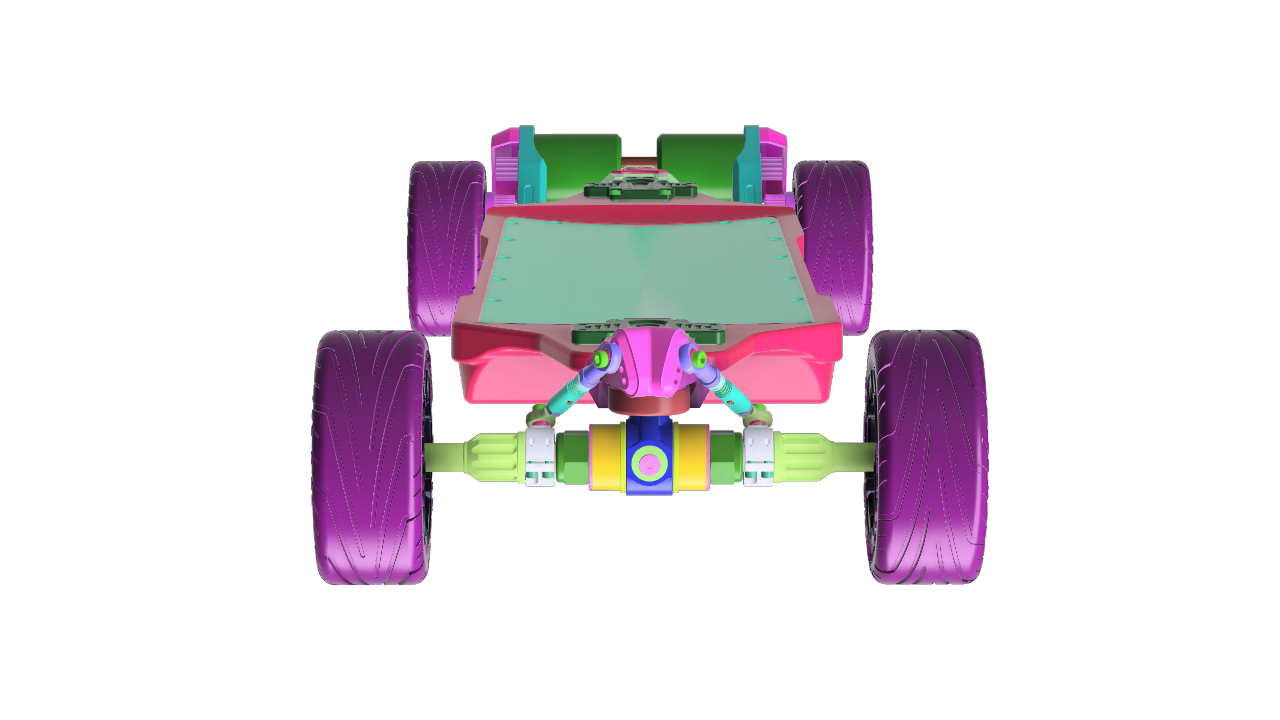
4.1 Understanding Pivot Shaft Trucks
Main Shaft and Bearings: The upper truck plate supports a central shaft, which is, in turn, supported by two large bearings. A bolt through a solid titanium CNC axle anchored to the CNC aircraft aluminum vertical shaft rides on four bearings, pivoting smoothly as the axle tilts, enabling precise weight transfer during turns.
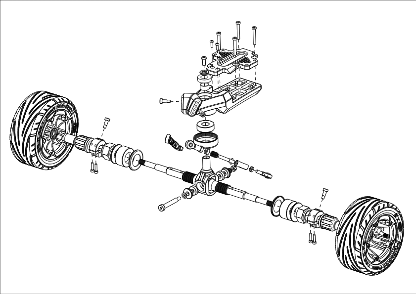
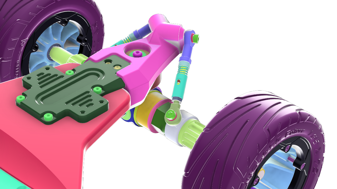
Front Pivot Shaft Truck
Spring-Loaded Steering Tie Rod: The tie rods connect the truck's upper CNC aircraft aluminum base plate to the axles, using springs to damp steering motion, ensuring no bind from zero to 15 degrees of tilt. The parts work in unison to produce smooth, controllable, and comfortable turns at high speeds.
Adjustability: You can adjust the tie rods and bushings to widen (increase) or tighten (decrease) the turning radius and ride stiffness. Tune the SE1 for freestyle street carving, all-terrain technical turns in tight spaces, or stability when cornering and road racing on high-grip asphalt.
How It Works: When you lean the deck to turn into a corner, the steering tie rods pivot the main shaft, axles turn, and the bearings make everything happen smoothly. The tie rods provide a mechanical self-correcting advantage, while the pin-through axle keeps everything aligned.

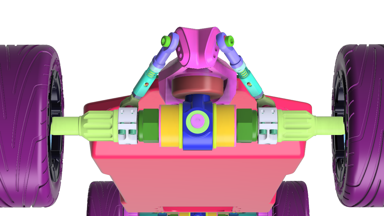
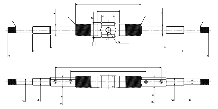
Rear View, Rear Pivot Shaft Truck With Motors
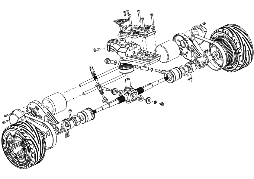
Rear Pivot Shaft Truck
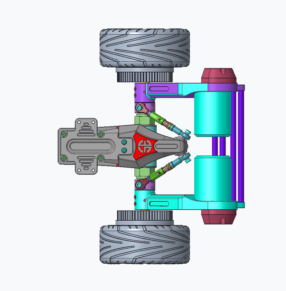
Top View Rear Pivot Shaft Truck

Spring Loaded Steering Tie Rod
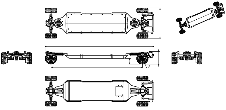
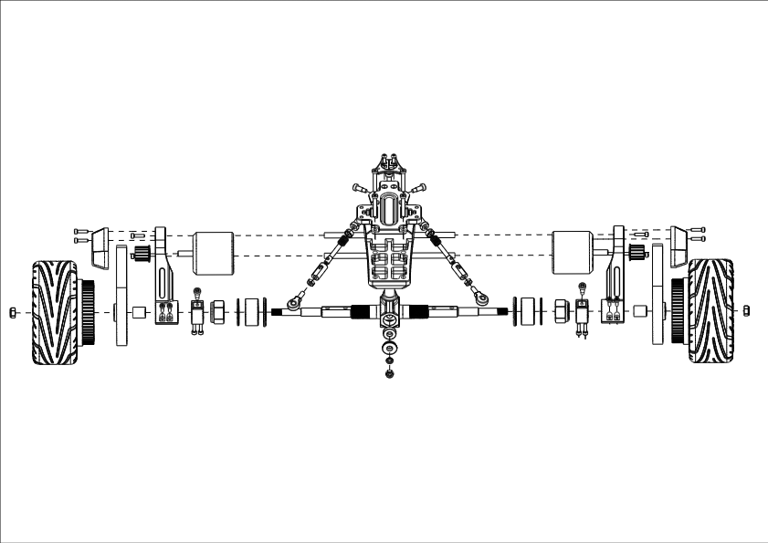
SE1 Drawings
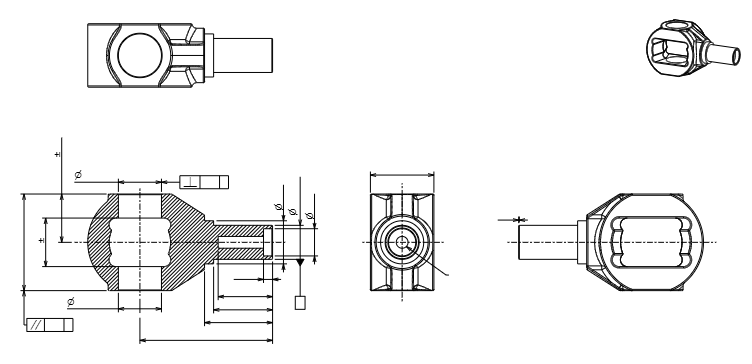
CNC Aircraft Aluminum Pivot Shaft
CNC Titanium Axle
Rear Pivot Shaft Trucks
4.2 Adjusting Steering Tie Rod Angles
The steering tie rods control the SE1's turning radius and responsiveness. Adjusting their angle lets you increase stability for high-speed riding or tighten the turning radius for increased agility.

Options For Tie Rod Angle Adjustment
4.2.1 Tools Required
-
10mm open-end wrench x 2, (included in SE1 tool kit)
-
hex key (included)
4.2.2 Increasing/Decreasing Turning Radius
Purpose: A larger/wider turning radius with a lower tie rod angle improves stability at high speeds. A tighter turning radius and a higher tie-rod angle enhance agility in lower-speed, extra-tight corners (e.g., street carving).
Locate Tie Rods: Each tie rod connects the truck's base plate to the axle—the steering tie rod angle option holes are on the ends of each truck's CNC base plate. The adjustment bolt is on the outer end of each tie rod fish eyeball joint.
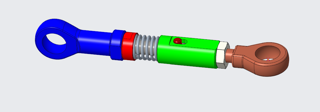
Steering Tie Rod
Increase Turning Radius (More Stability):
-
Use the wrench to loosen the male shape tie rod's jam nut.
-
Unscrew the bolt from the CNC truck base that anchors the steering tie rod and select a lower hole on the vertical row of options to lower the tie rod angle. This lower angle adjustment reduces the truck's turning action when a rider tilts the deck from 1 to 15 degrees. The sensitivity is reduced and stability at high speeds increases when lower angle steering tie rod angles are are selected.
-
Tighten the tie rod bolt and rod end jam nut to secure the tie rod in the new angle position. Left and right tie rods should always be set to the same angle bolt-hole options. Repeat for all four tie rods (two per truck).
-
Tie rod length usually does not need to be changed when adjusting their angle. After adjusting the angles check to confirm there is no loose sloppy play or bind due to steering link lengths. With the tires off the ground, hold a wheel in each hand and turn the axle of the truck back and forth. If the steering links springs are not loose so the truck system operates smoothly then great. If not then shorten the tie rods, equally on the left and right, a half or one full turn at a time until there is no sloppy play. If the tie rod bolts are difficult to install into the truck base plate then the tie rod lengths need to be longer. Do not change the tie rod spring's pre-load tension, change the tie rod length by adjusting the male shaped tie rod end.
-
Always keep left and right tie rods at the same angle settings.
-
It is critical to check alignment of the truck axles and wheels with a string if tie rod lengths are changed. (See Section 4.4)
Decrease Turning Radius (More Agility):
-
Loosen and detach the truck base tie rod adjustment bolts.
-
Raise the tie rod angle by selecting a higher bolt hole on the front or rear truck CNC base plate row of options. This decreases the turning radius of trucks when the deck tilts 1-15 degrees, allows for tighter turning action and more rider input sensitivity for low speed freestyle carving.
-
Tighten the tie rod anchor bolts in their new anchor hole option locations. Use medium—to light-strength bolt lock glue on all tie rod bolts for extra safety. High strength thread lock glue is not recommended.
-
Tie rod length should not need to be changed when adjusting their angle. After adjusting the angles, check to confirm there is no loose, sloppy play or bind due to steering link lengths. With the tires off the ground, hold a wheel in each hand and turn the axle of the truck back and forth. If there is loose play in the truck system, then shorten the tie rods, equally on the left and right, a half or one full turn at a time until there is no sloppy play. If the tie rod bolts are difficult to install into the truck base plate, then the tie rod lengths need to be longer. Do not change the tie rod spring's pre-load tension, change the tie rod length by adjusting the male shaped tie rod end.
-
Always keep the left and right tie rods at the same angle settings.
-
It is prudent to always check alignment of the truck axles and wheels with a string if tie rod lengths are changed. (See Section 4.4)
-
Always remember to keep the tie rod jam nuts tight when riding.
Test the new e-board settings by riding the board and making a few turns. Adjust the tie rods more if needed until you find your ideal turning radius.
Tip: Select the terrain's lowest possible angle setting option based on the tightest turn expected to maximize stability at low and high speeds.
Torque: Tighten bolts, but don't over-tighten to prevent loosening or bolt head damage. Low to medium strength thread glue helps keep bolts tight without seizing up later.
4.2.3 Fine-Tuning Spring-Loaded Steering Links
Purpose: Pre-loaded tension adjustments should not be necessary unless loose play occurs in the spring-loaded tie rods.

Tie Rod Steering Link
Process:
-
Tighten Springs:
-
Turn the spring tension bolt in or out to set preload spring tension.
-
Adequate preload tension compresses the spring, ensuring there is no loose, sloppy play in the compression-dampening spring-loaded steering tie rods.
-
Tip: Hold the axle and turn side to side. If loose play is observable in the tie rod springs, further fine-tuning adjustment is required. The truck system must be tight, smooth, and solid when turning action is initiated from the neutral position to the left and right front to back.
Warning: Overtightening springs can cause a pivot shaft bind, while over-loosening allows for loose play. Adjust tie rod spring preload tension until the system works smoothly.
4.3 Bushing Adjustment for Ride Feel
Bushings are polyurethane cushions in the trucks that control how easily the board tilts when you lean. Adjusting their preload tension with the large lock nut changes the SE1's ride feel. Adequate preload (without over-tightening) ensures a stable ride at higher speeds. Less preload tension on the bushings allows for quicker turning, enhancing freestyle agility. By default, the bushings in the front are softer than those in the optimizes for control. Fine-tune the preload bushing tension settings until you find the sweet spot and have fun.
Tools: Large Wrench
Process:
-
Prepare: Start with equal bushing preload tension in the front and rear and test-ride the board.
-
Stiffen Ride (More Stability):
-
Tighten the large axle lock nuts on the front and/or rear trucks (clockwise, 1/4 turn at a time).
-
Tightening the large lock nut compresses the bushings, increasing the compression-damping resistance.
-
Do not overtighten or distort the shape of the donut bushings. Overtightening can also cause instability, so find the sweet spot.
-
-
Soften Bushing Preload:
-
Loosen the nut (counterclockwise, 1/4 turn) to allow for more turnability, which is ideal for lightweight riders or tight, quick turns. (do not loosen so much that there is loose play and the bushings spin easily on the axle; this is too loose)
-
Balance: Adjust both trucks equally. Tighten the lock nuts to your desired preload tension to fine-tune and balance the SE1's performance.
Test: Ride in Low or Eco-speed mode to learn about responsiveness. Adjust to perfection in 1/4 turn increments.
Bushings: Four different rubber density bushings exist, ranging from 30A to 60A. The default is two 40A on the front and two 60A bushings on the rear truck. If you change bushings, be sure to reassemble the trucks carefully, re-square the axles with a string, and tighten all nuts and bolts.
4.4 Squaring Trucks with a String
Squaring ensures the trucks are perfectly aligned and square with the front, preventing the board from pulling to one side. Checking this alignment after truck disassembly is critical, and it should be done periodically, especially after bumpy rides on rough roads or heavy use.
Trucks Must Be Square For Stability
4.4.1 Tools and Setup
-
Squaring string (included in tool kit)
-
10mm and 10mm wrenches
-
Allen hex wrench
-
Tape
-
Flat, level surface
4.4.2 Step-by-Step Alignment Process
Prepare:
-
Ensure the tires have equal 35 psi of air pressure (Section 4.3).
-
Make sure all wheels, nuts, and bolts and bushings are tight.
Tie rod spring tension:
Tip: For pivot shaft truck alignment adjustments, it is recommended that the tie rod bolts be removed from the axles, not the the bolts attached to the CNC truck base plate. If the tie rod to axle anchor bolts do not line up easily with the axle clamps the axle/steering tie rod lengths need adjustment. Do not force the bolts into the axle clamps. Start screwing the bolts in by hand before using a hex wrench to tighten.
Pre-load Tension: With the steering tie rod lengths of the front and rear trucks equal, when attached to the truck CNC base plate, they must be adjusted to maintain tension on the axle and tie rod springs so there is no loose play in the trucks.
Test: When the axle is shaken forward and backward, left and right under the skateboard deck, there cannot be any loose play.
Adjust: If there is play in the truck assembly, then shorten the male shape steering tie rod ends evenly on the left and right sides until there is no sloppy play.
Re-test: At neutral position, when the truck sits with adequate, even tension on both tie rods, the springs will not have loose play, when turning the axle left or right, or pushing the axle forward or backwards under the deck. With sufficient adjustment, smooth turning action will occur so that the trucks can perform perfectly.
Square The Trucks With A String:
Rear Tire: Starting with the rear trucks, attach one end of the squaring string to the center of the rear-facing side of the rear tire surface.
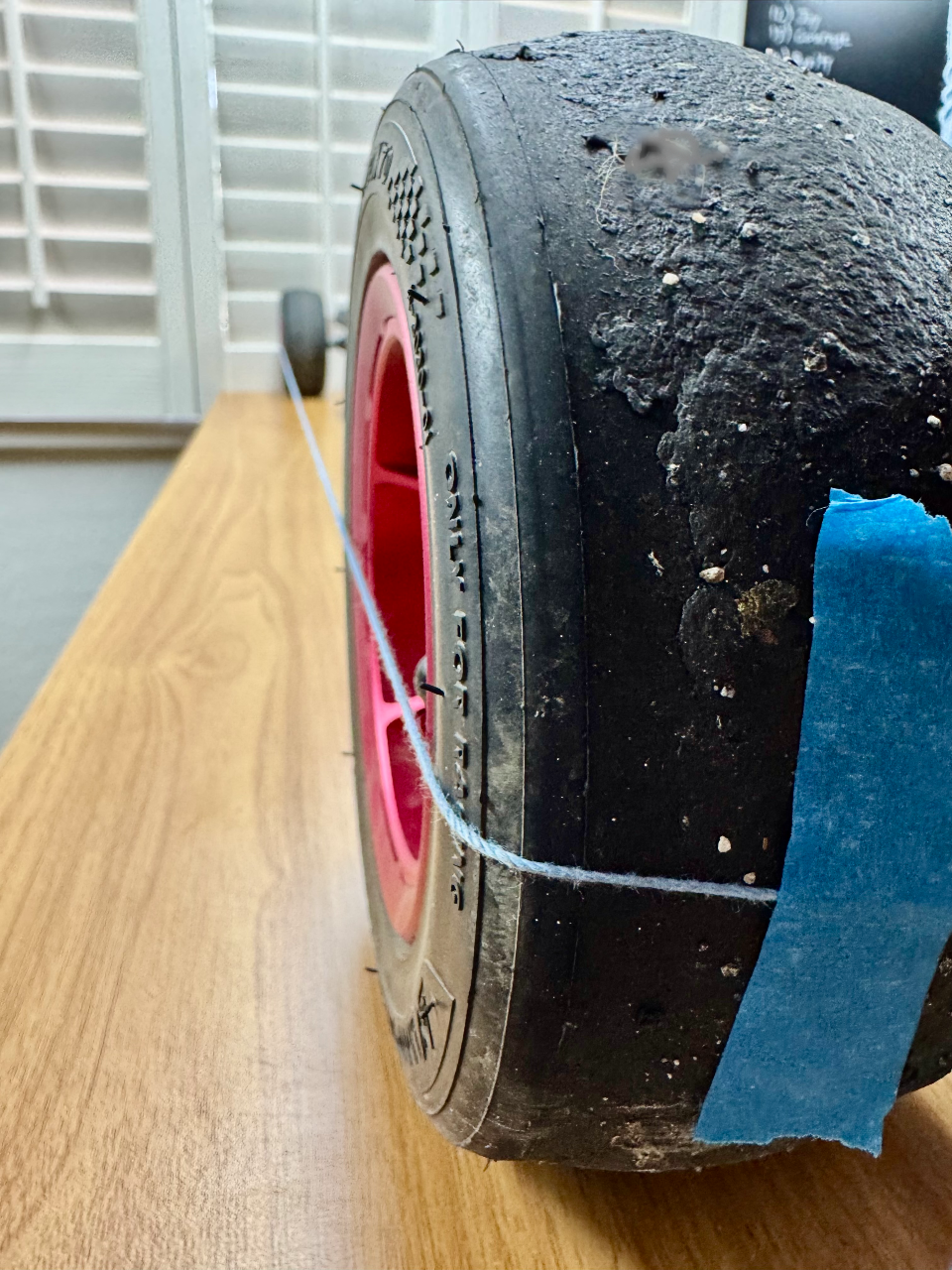
String Alignment Method:
Front Tire: Pull the string taut around the outside of the rear tire to the center of the front-facing side of the front tire, ensuring the string is not loose but is straight and touching the inner sections of the tire sidewalls on both the front and rear. Then, tape the string to the front side of the front tire.
Check for Alignment: Starting with the end of the string taped to the rear side of the rear tire, check to see if the front section of the rear tire sidewall is or is not slightly touching the straight horizontal string.
Measure Alignment:
-
String Gap: Suppose the front section of the rear tire sidewall has a big or small space between the string and the tire. In that case, the steering tie rod length on the same side of the truck must be shorter, and the opposite side tie rod length must be longer equally so that the tire moves farther forward. Adjust both side tie rod lengths equally until the tire sidewall slightly touches the string.
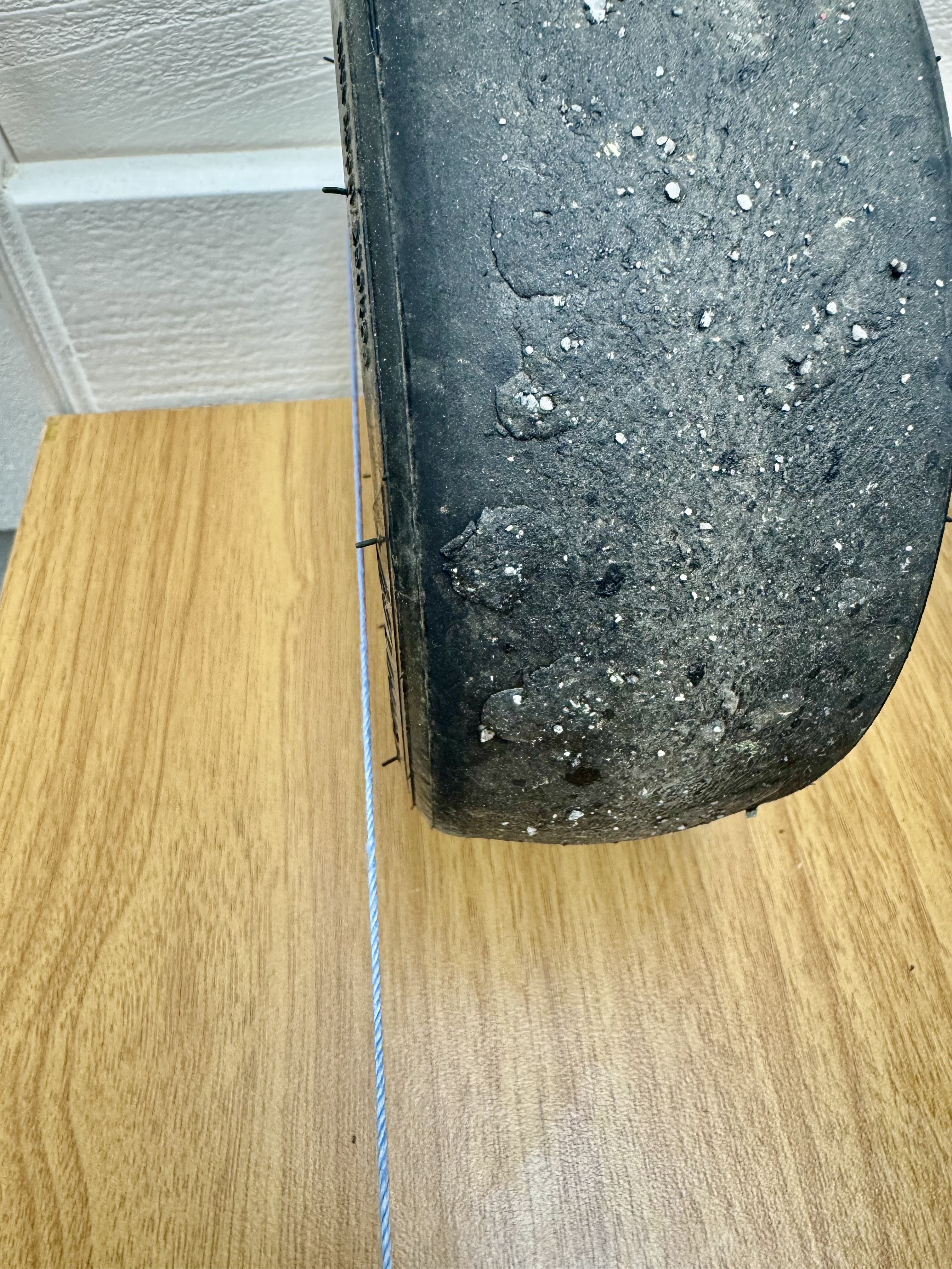
Space between tire wall and string:
String Impact: Suppose the front section of the rear tire sidewall impacts the string, distorting its straight-line path to the front tire's sidewall. In that case, the steering tie rod must be lengthened on this side of the truck so that the tire moves towards the rear, and the opposite side tie rod is shorter equally so that the string is only slightly touching the sidewall and straight without heavy impact.

String impacts the tire sidewall:
Adjust Trucks:
-
Lengthen And Shorten Each Rear Tie Rod: If the string alignment is off and not barely touching the front section of the rear tire sidewall.
-
Loosen and detach both the right and left side steering tie rod bolts attached to the rear axle.
-
Loosen the jam nuts on both non-spring sections of the two tie rods. (Tie rods should be equal or very close to lengths to begin with)
-
Turn one tie rod end one turn or a half turn in or out.
-
Any change made to a tie rod on one side of the truck must also mirror or copy the number of turns in the opposite direction to the tie rod on the other side.
-
Reattach the tie rods to the axle clamps using the bolts, and then check the tire sidewall alignment with the string again.
-
-
Test: After shortening one tie rod and lengthening the opposite tie rod end, if the string does not touch slightly or if there is a heavy impact on the front section of the rear tire sidewall, the steering alignment is still off. Shake the axle to ensure there is no loose play in the truck system. Take the time to align the system correctly. Another adjustment of the rear tie rod ends, either half a turn or a complete turn, in opposite directions is needed until the string lines up perfectly.
-
Lengthen and Shorten Each Front Tie Rod: After adjusting the front tie rods, check the rear tie rod and axle steering alignment with a string. If a fine-tune adjustment to the rear tie rod lengths is an issue, make the change before finishing to confirm everything is tight and in excellent condition. If not, stop, go back, and adjust until it is. Ride the e-board around the block at a slow to medium speed to confirm everything is tight and operational before embarking on a long-distance ride, traveling to the start point of a destination adventure ride, or participating in road racing.
4.5 Checking Mechanical Alignment
Proper pre-ride component operation testing ensures a smooth and predictable riding experience, preventing premature component failure. Check for issues regularly, especially after impacts (e.g., hitting curbs or other obstacles).
Process:
-
Visual Inspection: With the board upside down, ensure the trucks' axles are straight, square, and centered. Look for bends or offsets.
-
Wheel Spin Test: Spin and shake each wheel by hand. It should rotate freely without wobbling or grinding due to bearing failure. Wobble indicates a bearing failure, loose wheel nut, or the steering tie rods may be out of adjustment.
-
Belt Tension Test: Check motor belt tension; if loose, tighten it by removing the belt covers, loosening the motor bolts, pulling the motor back onto the motor hangars until the belt is tight, and re-tightening the motor bolts.
-
Tip: Use a flathead screwdriver to pull motors tight to ensure belt tension while tightening the motor bolts.
-
Truck Adjustment Check: Loosen all pre-load tension on donut bushings before performing this test to ensure the system is correctly adjusted. Tug on each truck to confirm that the baseplate bolts, tie rods, bearings, and pivot shafts are tight, with no loose play. When holding two wheels on an axle at neutral, turn the axle left and right, then tug forward and backward to check if the truck is loose or tight. If there is significant play, re-adjust the steering tie rods as needed.
-
Tie Rod Alignment: Ensure the upper truck base plate tie rod anchor bolt setting option selected is equal on both the left and right sides of the front and rear trucks.
-
Tip: When riding the electric skateboard, be aware of unusual, unexpected sounds or performance issues.
Warning: Deferred or neglected maintenance, unchecked alignment, and/or a dirty e-board allow for premature component failure and unsuccessful rides. Be responsible, proactive, and tidy so your e-board will be ready and available to ride for many years to come.
5.1 Issues and Solutions
This section lists issues, their causes, and straightforward solutions to keep your SE1 running smoothly.
Flat Tire – Replace the Tire Tube:
-
1) Release all air pressure from the tire tube by pressing the tire tube’s needle in the center of the end of the valve with your fingernail or a small pointed object.
-
3) Loosen the five bolts holding the outer ringing onto the wheel.
-
4) Install the new tire with tube carefully so the tube does not get pinched and re-install the outer ring.
-
Pro Tip: Before inflating the tire tube, be sure the tube is evenly sitting inside the tire without twists or pinched sections. Spin the deflated tire and tube on the wheel until the valve aligns correctly through the hole without unusual distortion. Never ride on a low or flat tire.
Loose Nuts and Bolts:
-
Solution: Check all nuts and bolts. Tighten with a hex key or wrench. Inspect regularly.
-
Pro Tip: Apply a low-strength thread locker glue to bolts for extra security. Do not use high-strength glue on small nuts and bolts that will cause bolts to strip.
5.2 Thumb Throttle Remote
Wheel Direction Reversal:
-
Symptoms: The board moves backward when pushing the throttle upward.
-
Solution: Press the function button twice to reverse the wheel direction. The arrow on the remote’s LED screen will switch directions.
-
Pro Tip: To make the SE1 go in reverse, press the function button twice and slowly spin the thumb throttle wheel up to accelerate in reverse.
-
Warning: Do not use this function casually because switching directions can cause an accident if the rider gets confused.
-
See section 7.6.6 for more info.
Unresponsive Power Buttons:
-
Symptoms: Remote or e-board fails to turn on.
-
Solution: Charge the remote. For the board, plug in the charger to the wall and e-board. After charging, press the power button firmly. If remote is still unresponsive it must be replaced. If e-board is still unresponsive, remove the battery box cover, disconnect the battery plug from the yellow plug from the electronic speed control, reconnect, then retry the power button. Confirm that the power button and charge port are plugged in.
-
Power Buttons Do Work: If there is still no response, the battery has severe fatal damage. Do not attempt to repair an unresponsive battery. The only solution is to replace the battery.
-
Warning: Always keep the rubber dust cap over the battery charge port when not charging. If water or a metal object comes in contact with the port, the battery can short out and may not power on after unplugging to restart.
5.3 Motor or ESC Malfunctions
The Hobbywing motors (6350 2000W or 6584 3300W) and ESC (14S/16S) power the SE1. These steps address motor and ESC issues safely.
Motor Not Responding:
-
Symptoms: Wheels lack power, motor clicks, or feels hot after power buttons are turned on.
-
Solution: Check belt tension (Section 5.1). Confirm battery charge (Section 4.1). Inspect motor cables for loose connections or damaged wires. Reset ESC: Disconnect the battery, wait 10 seconds, and reconnect. Contact support if the issue persists.
5.4 Battery Performance Concerns
The Samsung 25R, or 50S (14S4P 25S, 14S4P 50S, or 14S6P), or Molicel P45b (16S3P or 16S5P) Lithium-Ion batteries are reliable and these solutions address most battery issues.
-
Range is short after fully charging. 14S4P 25R 518Wh battery has a shorter range than 14S4P 50S 1018Wh capacity so a shorter range is normal for a 25R battery.
-
Battery does not accept or demonstrate complete charging with a green light. If power button does not light up, or the motors do not spin when battery is fully changed then the battery must be replaced.
5.5 When to Contact Support
Contact SE1 support if issues persist after troubleshooting or involve critical components.
When to Reach Out:
-
Unresolved issues after trying this chapter’s fixes.
-
Safety risks: Bent axles, warped deck, overheating battery, damaged remote, or electrical faults.
-
Warranty claims for defects within 6 months.
-
Need for parts: Remotes, axles, belts, or bushings.
-
Complex repairs: Motor, ESC, or battery issues needing professional service.
How to Contact:
-
Online: Take some photos and a video. Attach them to an email and describe the issue in detail to info@skateboardselectric.com. Submit a ticket with:
-
Order number
-
Detailed issue description
-
Photos/videos (e.g., bent axle, error codes)
-
Troubleshooting steps attempted
-
Prepare: Provide the board’s serial number (on the underside of the trucks) and purchase details. Note troubleshooting steps for faster assistance.
Shipping: Use original packaging for warranty repair shipping (Section 2.1).
Warning: Do not repair batteries, motors, or ESCs yourself. Doing so voids the warranty and risks injury.
6.1 Safety Gear Recommendations
Proper safety gear minimizes the risk of injury during rides.
Helmet: For road racing and long-distance adventure rides, wear a DOT-certified full-face or skate-specific helmet. The minimum is a basic helmet (e.g., ASTM F1492 or CPSC-compliant) in case the unexpected happens.
Lights: If there's a chance it will get dark before your ride ends, always bring lights. All SE1 e-boards include easy mount pre-drilled holes for our top quality, self-powered, proprietary, 3600L light kit: https://skateboardselectric.com/products/se-3600l-light-kit-for-electric-skateboard
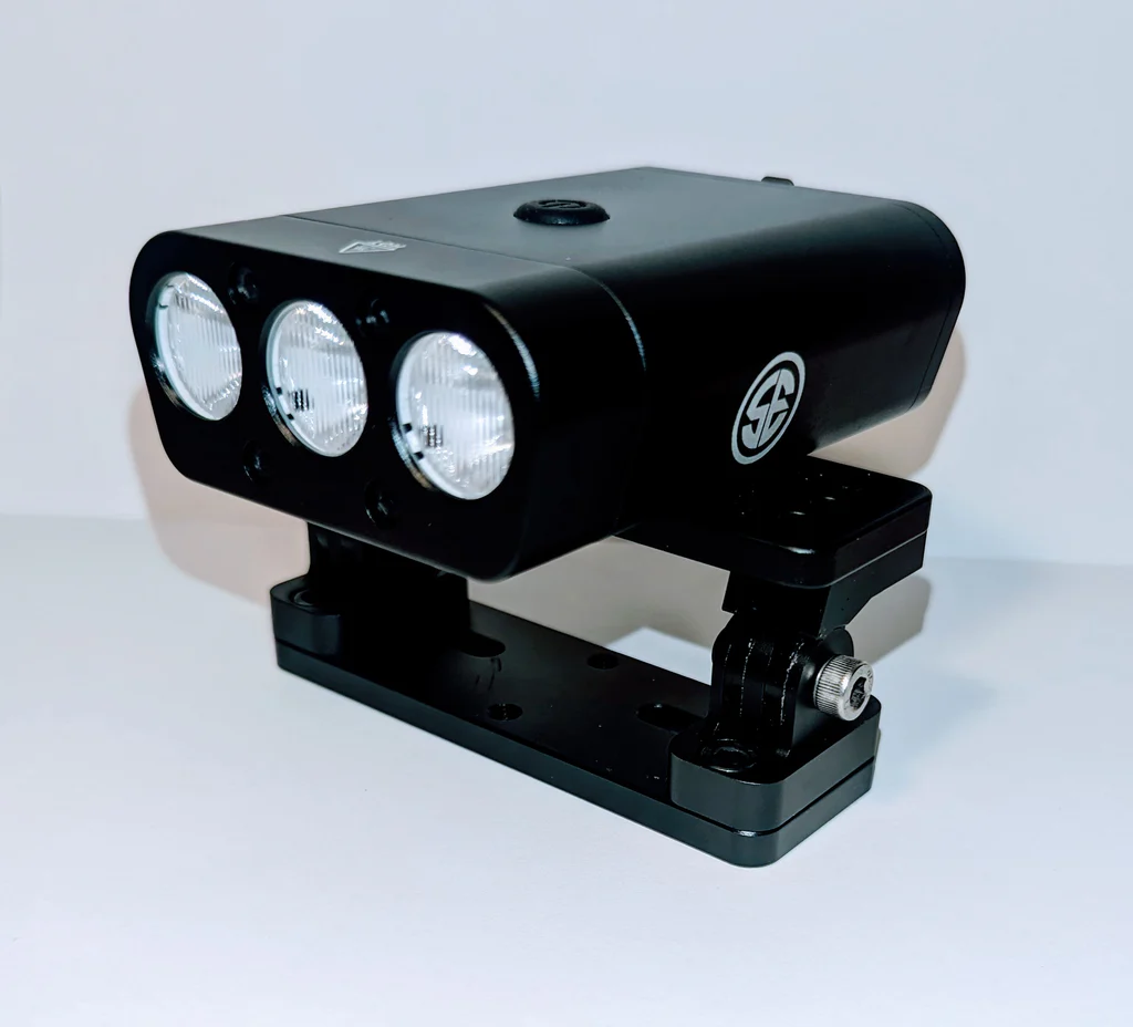
3000L Self Powered Front Headlight
Chest and Elbow Pads: Use durable pads with hard shells to protect joints during falls. Choose breathable, adjustable models for comfort. https://leatt.com/us/body-protector-5-5-evo-v25.html
Wrist Guards: Select guards with rigid splints to prevent wrist fractures. Ensure they allow for hand mobility with the thumb throttle remote control. https://skateboardselectric.com/products/wrist-guard-battle-gloves
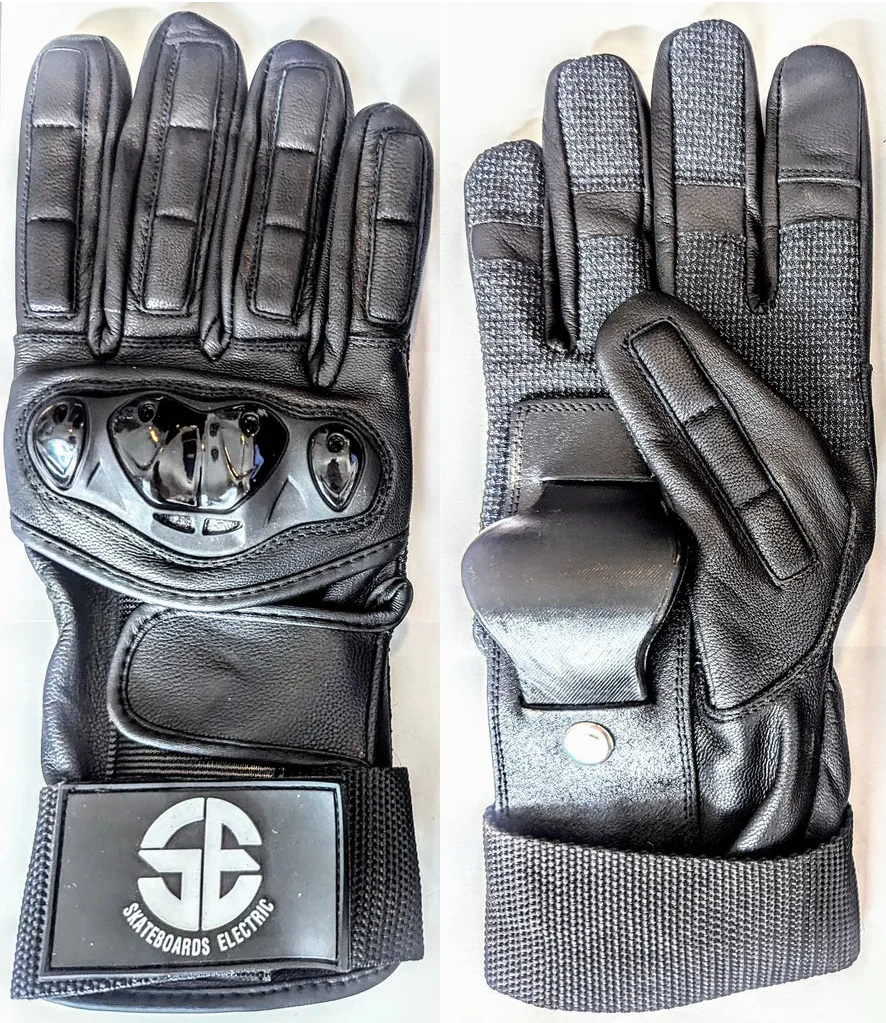
Battle Gloves
Closed-Toe Shoes: To maintain deck traction, control, and safety, wear sturdy, flat-soled shoes with good grip. Do not wear sandals or loose-fit footwear.
Knee Protection: Rather than waiting and learning the hard way, hopefully, you won't need it, but we recommend investing in good-quality knee protection. https://leatt.com/us/knee-brace-x-frame.html
Hip Protection Gear: Consider padded shorts or hip protectors. https://leatt.com/us/impact-shorts-3df-5-0.html
Jacket: A durable fabric shell, such as a Racecar Fire suit or Hoodie, worn over your shoulder and chest pads, provides complete protection.
Pants: Durable fabric, dirt bike-style pants with over-knee pads complete a full armor protection suit that works excellently for ESK8 adventures and racing.
6.2 Riding Etiquette and Local Laws
Responsible riding ensures safety for you and others while complying with local regulations.
Know Local Laws: Research the regulations for electric skateboards in your area. Some regions restrict e-boards to specific areas. Watch for walking-only zones and street signs with ESK8 restrictions.
Yield to Pedestrians: Slow down when approaching walkers, cyclists, or pets in crowded areas to maintain control.
Respect Traffic Rules: When riding on roads or shared paths, obey stop signs, signals, and right-of-way rules. Avoid weaving through traffic. Stop lights and stop signs apply to esk8ers, so always exercise caution.
Be Courteous: Signal turns with hand gestures and maintain a predictable path. Please pass on the left and announce your presence so other riders are not startled when you pass them.
7.1 SE1 and SE1 Dragon Models
SE1:
Description: All SE1, SE1 Dragon, and SE1 Pro models include the same patented Pivot Shaft Trucks and two carbon fiber deck options for maximum stability. The tires, wheel options, and Hobbywing high-performance speed control with four-speed modes are the same. The SE1 is compatible with easy-to-install upgrades to increase performance, so when you’re ready, turn your SE1 into a Dragon with bigger 6384 3300W motors and a 16S Molicel P45b battery!
Configurations:
-
Deck: 40” Standard Length with Bald Racing Tires
-
Deck: 40” Standard Length with All-Terrain Tires
-
Deck: 49” XL9 with All-Terrain Tires
-
Deck: 49” XL9 with Bald Racing Tires
SE1 Dragon:
Description: SE1 model e-board deck and trucks with enhanced torque and top-speed capabilities.
Configurations:
-
Deck: 40” Standard Length with Bald Racing Tires
-
Deck: 40” Standard Length with All-Terrain Tires
-
Deck: 49” XL9 with All-Terrain Tires
-
Deck: 49” XL9 with Bald Racing Tires
Note: Both models feature IPX-6 water resistance, a 5A charger, and Hobbywing electronics.
-
Install the truck bolts to the trucks.
-
Plug in the motors by matching the cables from the motors to the corresponding wires on the speed controller.
7.2 Motor Options (Hobbywing 6350 2000W, 6584 3300W)
Hobbywing 6374 2000W:
-
Power: 2000W per motor (dual belt drive, 160 KV, 60T)
-
Performance: Delivers smooth acceleration and reliable torque for street and all-terrain riding Top Speed 40mph.
-
Compatibility: Works with the included 14S/16S Electronic Speed Controller.
-
Warning: If you have an SE1 with 6374 2000W motors, do not use a 16S battery. Only use a 14S battery because the 6374 motors because they are incompatible with a 16S battery. If you upgrade your battery to 16S, you must also upgrade the motors to 6384 4500W.
Hobbywing 6384 4500W:
-
Power: 4500W per motor (dual belt drive, 140 KV, 60T, 1:4 ratio gear)
-
Performance: Provides aggressive acceleration and higher top speeds (up to 45+ mph in Sport+ mode). Optimized for road racing and demanding terrains.
-
Compatibility: 6384 motors require a 16S battery and the Hobbywing ESC set to 16S for full performance but is compatible with 14S batteries at reduced output.
7.3 Battery Options and Range
SE1 Battery Options:
-
14S4P Samsung 25A battery: Medium speed mode, flat paved surfaces - 11 miles
-
14S4P Samsung 25A battery: High Speed uphills and over rough terrain - 6 miles
-
14S4P Samsung 50S battery: Medium speed, flat paved surface - 22 miles
-
14S4P Samsung 50S battery: Max speed mode, up hills and over rough surfaces - 15 miles
-
14S6P (Extra Long deck only): Medium speed flat paved surface - 35 miles.
-
14S6P (Extra Long deck only): Top speed on hills and rough surfaces: 27 miles
-
With included 6374 2000W 170Kv motors, and 35 PSI tire pressure:
SE1 Dragon Battery Options:
-
16S3P battery: Medium speed, flat paved surface - 20 miles
-
16S3P battery: Max speed mode, up hills and rough surfaces - 15 miles
-
16S5P (Extra Long deck only): Medium speed flat paved surface - 30 miles .
-
16S5P (Extra Long deck only): Top speed on hills and rough surfaces: 20 miles
-
Range estimates decrease when motors are upgraded.
-
It is recommended to plan rides that are 3/4 of the battery's range capacity, so battery life is never an issue.
-
5A Chargers are small and lightweight, so they can be carried in a backpack to recharge. 1.5-2 hours to recharge the 16S3P battery. 2-2.5 hours to recharge the 16S5P battery.
-
With included 6384 4500W 140Kv motors, and 35 PSI tire pressure:
7.4 Deck Dimensions (XL9 and Standard)
Standard Deck:
-
Total Length: 40 inches
-
Foot Stance: 30 inches
-
Board Length (with trucks): 57 inches
XL9 Deck:
-
Total Length: 49 inches
-
Foot Stance: 39 inches
-
Board Length (with trucks): 65 inches
7.5 Tire Options and Specifications
160mm x 72mm Bald Soft Rubber Road Racing – All Terrain Tires:
-
Durometer: Soft rubber (optimized for speed and esk8 racing)
-
Pressure: 30-35 psi (recommended 30 psi)
-
Features: Solid rubber 50A, designed for maximum speed and grip on smooth high-grip tracks. Less traction on wet surfaces but tested for durability and extended performance on all types of surfaces.
-
Pro Tip: Check tire pressure before and halfway through every ride, especially if the rider weighs over 180 lbs. (Section 4.3).
190mm x 80mm Off-Road All Terrain – dirt
-
Features: Aggressive off road tread pattern for slow and high speed riding.
7.6 Weight, Dimensions, and Ride Height
Weight:
-
SE1 Mini Dragon and Dragon with Standard Deck: ~41 lbs
-
SE1 Mini Dragon and Dragon XL9 Deck: ~48 lbs
Dimensions:
-
Total Length:
-
Standard Deck: 57 inches (including trucks)
-
XL9 Deck: 65 inches (including trucks)
-
-
Tread Width: 15.5 inches (both models)
-
Deck Ride Height: Adjustable 1.75 – 3.1 inches (both models). Three deck height options.
-
Deck Foot Stance:
-
Standard Deck: 30 inches
-
XL9 Deck: 39 inches
-
Deck width: 10 inches
-
Additional Features:
-
Axles: Solid Titanium CNC (front and rear)
-
Trucks: Aircraft Aluminum CNC with Pivot Shaft Technology, 10 bearings (front), 12 bearings (rear), rubber bushings, adjustable spring-loaded steering tie rods
-
ESC Hobbywing: Adjustable 100A
-
14S battery setting, compatible with 2000W and 3300W motors.
-
16S battery and ESC settings are compatible with motors 4500W 6384, up to 5500W 63100
-
-
Remote Wireless: Two thumb throttle screen remotes (primary and backup)
-
Water Resistance: IPX-6 (resistant to light rain, not submersion)
-
Charger: 5A, compatible with 14S or 16S battery options


7.6 Remote Functions and Operating Instructions:
1. Power On:
Press and hold the Power Button for 1 second if the remote is powered off. You will feel a vibration, and the remote will enter pairing mode. The OLED screen will display either the main interface or a “not connected” message, based on the connection status. - **Mainboard Activation**: After powering on the remote, briefly press the mainboard power button to turn it on and initiate pairing mode. Note: The main interface appears on the OLED screen when the device is connected, and the mainboard power indicator light remains continuously on.
2. Power Off:
Press and hold the Power Button for 2 seconds to turn off the remote when it is powered on. The remote cannot be powered off if it is connected to a moving skateboard. However, the mainboard can be turned off at any time by pressing and holding its power button for 2 seconds. If the mainboard shuts off while the remote stays on and is connected, the screen will display “Not Connected” and vibrate once as a notification. If the remote powers off while stationary, the mainboard automatically enters standby mode (approx. 24 hours). - **Auto Shutdown**: When the remote and mainboard are connected and inactive for 5 minutes while stationary, the remote will automatically power off, and the mainboard will enter standby mode. If disconnected, both devices will shut down automatically after 5 minutes of inactivity. The next startup will require manual activation.
3. Pairing Remote To E-board:
Ensure both devices are powered off. Press and hold the mainboard power button for 5 seconds; the indicator light will flash red quickly, indicating that pairing mode is activated. Next, press and hold the remote’s Power Button for 5 seconds. The screen will show a pairing prompt, and you will feel two short vibrations followed by one long vibration when pairing is successful. After pairing, configure the skateboard settings such as 2WD/4WD, speed units, gear ratio, wheel diameter, motor KV, and motor pole pairs. The mainboard indicator will light solid red, confirming successful pairing. **Note:** Use the scroll wheel to adjust settings, then press the Power Button to save your changes. After settings are complete, the remote will return to the main function screen.
4. Battery Indicator:
Remote Battery Status: The remote features five battery level bars, each representing approximately 20% of the total charge. Once the battery drops below 10% (about 30 minutes of use remaining), the screen shows a low battery warning, and you will feel two long vibrations. At around 5% battery (approximately 15 minutes remaining), another warning will occur, accompanied by two long vibrations. If the battery voltage drops below the safe operating level (3.4V) while the remote is connected and stationary, it vibrates briefly and powers off automatically.
Skateboard Battery Status: The skateboard has 10 battery bars, each indicating approximately 10% charge. A drop below 25% triggers a warning on the remote screen, accompanied by two vibrations. At below 10%, a second warning occurs. When the battery reaches 0%, power output is disabled, allowing only braking to occur. It is recommended that usage stop at this point. The mainboard will respond only to braking. Extreme braking may consume power and damage the battery, while regenerative braking remains inactive.
5. Throttle / Brake Control:
Push the Throttle Wheel forward to accelerate and pull it backward to brake. Ensure the throttle wheel is in the natural neutral position when powering on to avoid affecting throttle performance. If the throttle is not centered during power-on, the screen will prompt you to adjust it.
6. Skateboard Direction Switch:
To switch direction while moving forward, double-click the Function Button; the remote will vibrate once, and the screen will show a backward arrow. To switch to moving backward, double-click the Function Button again; you will feel another vibration, and the screen will display a forward arrow. This Function is only available when the throttle is centered, and the speed is under 3 km/h.
7. Gear Shift:
Press the Function Button once to shift to the next gear. You will feel a short vibration, and the gear icon will update on the screen. Note: This can only happen when the throttle is centered.
8. Data Viewing:
Press the Function Button on the main screen to cycle through various data points, including total mileage, trip mileage, real-time voltage and current, mainboard motor temperature, motor RPM, drive mode, gear ratio, wheel diameter, and motor pole pairs.
9. Cruise Control:
After powering on and maintaining a steady throttle level, press the Power Button once to engage cruise control. You can then release the throttle, and the skateboard will sustain its current speed. Any throttle, brake, or button input will immediately exit cruise mode.
10. Advanced Parameter Settings:
Press the Function Button 5 times consecutively to enter advanced parameter settings while connected. Follow the on-screen prompts for adjustments.
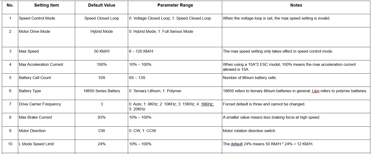
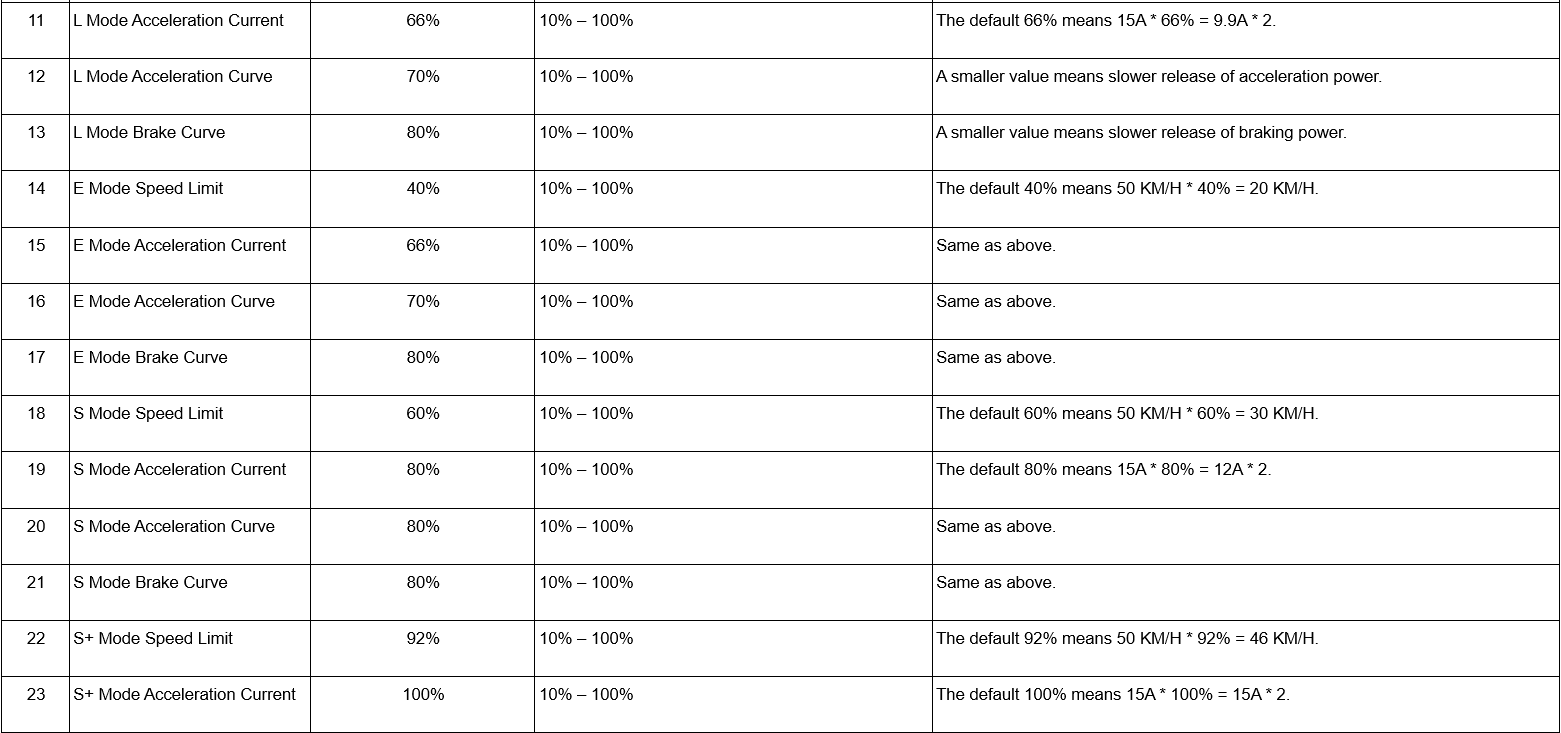
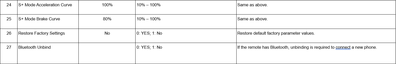
Default Remote Parameter Settings And Info
8.1 Customer Support Channels
Our dedicated support team is ready to assist with troubleshooting, warranty claims, part replacements, or general inquiries about your SE1 or SE1 Dragon.
Email:
-
Address: info@skateboardselectric.com
-
How to Use: Send a detailed description of your issue, including your order number and board serial number (located on the underside of the trucks), along with photos or videos of the problem and any troubleshooting steps you have attempted (Section 5.5). Expect a response during business hours (Monday through Friday, 9 AM-5 PM PST).
-
Best For: Technical issues, warranty claims, part orders not listed on the website (e.g., remotes, belts, bushings), or complex repairs.
Website:
-
How to Use: Submit a support ticket. Include the exact details by email (order number, serial number, photos/videos, troubleshooting steps).
-
Best For: Streamlined warranty claims, replacement part requests, or follow-ups on existing issues.
Warning: For safety-related issues, stop riding immediately and contact support to prevent injury or damage.
8.2 Online Resources and Community
Social Media:
-
Platforms: Follow Skateboards Electric on:
-
Content: Watch riding videos, view new feature announcements, and participate in giveaways or rider meetups.
-
Best For: Staying engaged with the SE1 community and learning from pro riders’ techniques.
8.3 Feedback and Suggestions
Your input helps us improve the SE1 and SE1 Dragon, ensuring they meet the needs of riders. We welcome feedback on performance, features, or support experiences.
New idea suggestions and comments:
-
Email: info@skateboardselectric.com
-
Describe your idea in detail, and attach photos/videos for clarity. We welcome all comments, ideas, and suggestions.
8.4 Warranty Information (6-Month Mechanical Reliability)
The SE1 and SE1 Dragon include a 6-month mechanical reliability warranty covering manufacturing defects, ensuring confidence in your purchase.
Coverage:
-
Defects due to manufacturing errors.
-
The warranty is valid for six months from the date of purchase.
-
To submit a claim, the purchase must be verified by the original owner with an order number and serial number (located on the underside of the trucks).
Claim Process:
-
Please email support at info@skateboardselectric.com with the order number, serial number, a detailed description of the issue, photos or videos, and the troubleshooting steps taken (Section 5.5).
-
Skateboards Electric support will evaluate the claim and provide repair or replacement according to warranty terms, so you can continue riding.
-
Pro Tip: Invest in an extended full coverage warranty from CPS. https://www.cpscentral.com/personal-transport-warranty-information/
8.5 CPS Add-On Warranty Details
The CPS (Consumer Priority Service) add-on warranty offers extended protection beyond the 6-month mechanical reliability warranty, covering additional scenarios for peace of mind.
Coverage:
-
Extends protection for up to 2 years (select at purchase).
-
Includes accidental damage (e.g., crash-related deck cracks, axle bends).
-
Provides priority repair or replacement services.
Exclusions:
-
Loss or theft.
How to Purchase an Extended Warranty:
-
Select the CPS add-on at checkout at https://skateboardselectric.com.
-
Review terms and pricing during purchase (pricing not provided here; see webpage link for more info about CPS warranty protection): https://www.cpscentral.com/personal-transport-warranty-information/
Claim Process:
-
Contact CPS support via their portal (linked in purchase email confirmation)
-
Submit a claim with the order number, serial number, issue details, and evidence (photos/videos).
-
Follow CPS instructions for shipping or repair.